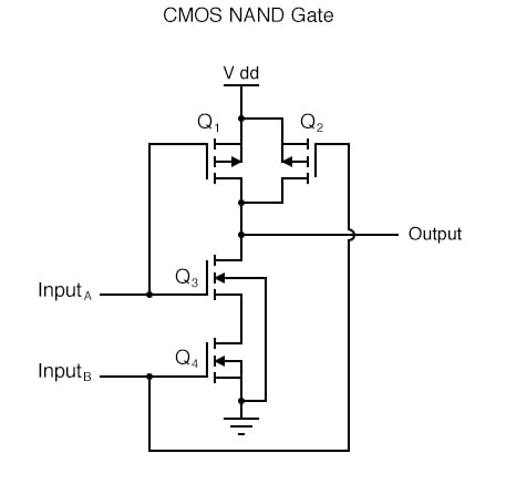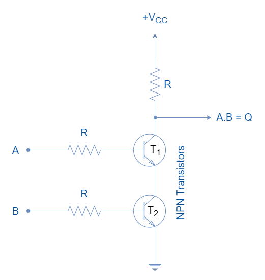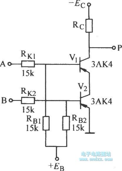

#TRANSISTOR DIAGRAM FOR A NAND GATE SERIES#
The following series of illustrations shows this for three input states (00, 01, and 10): Namely, if either of the inputs is grounded, transistor Q 2 will be forced into a condition of cutoff, thus turning Q 3 off and floating the output (output goes “high”).

Since this circuit bears so much resemblance to the simple inverter circuit, the only difference being a second input terminal connected in the same way to the base of transistor Q 2, we can say that each of the inputs will have the same effect on the output. Thus, a 1 in resulted in a 0 out, and vice versa. In the case of the open-collector output configuration, this “high” state was simply “floating.”Īllowing the input to float (or be connected to V cc) resulted in the output becoming grounded, which is the “low” or 0 state. In the single-input (inverter) circuit, grounding the input resulted in an output that assumed the “high” (1) state. This transistor has one collector, one base, and two emitters, and in the circuit, it looks like this: Unfortunately, a simple NPN transistor structure is inadequate to simulate the three PN junctions necessary in this diode network, so a different transistor (and symbol) is needed. Just as in the case of the inverter and buffer, the “steering” diode cluster marked “Q 1” is actually formed like a transistor, even though it isn’t used in any amplifying capacity. This schematic illustrates a real circuit, but it isn’t called a “two-input inverter.” Through analysis, we will discover what this Circuit’s logic function is and correspondingly what it should be designated as. Truth Table AND gate using NAND gate OR gate using NAND gate.Suppose we altered our basic open-collector inverter circuit, adding a second input terminal just like the first: Two Input Inverter Circuit There is the following expression of the 4-input NAND gate: If the number of inputs required is odd, any "unused" input can be held high by directly connecting it to the power supply using high "suitable" pull-up resistors. Just like AND, NOT, and OR gate, we can also form n-input NAND gate. The truth table and logic design are given below: There are 2 3=8 possible combinations of inputs. The NAND gate can be cascaded together to form any number of individual inputs. The Boolean expression of the logic NAND gate is defined as the binary operation dot(.). Unlike the 2-input NAND gate, the 3-input NAND gate has three inputs.

There are 2 2=4 possible combinations of inputs. In this type of NAND gate, there are only two input values and an output value. This is the simple formation of the NAND gate. These are the following types of AND gate: The 2-input NAND Gate The NAND gate is also classified into three types based on the input it takes. The value of Y will be true when any one of the input is set to 0.
#TRANSISTOR DIAGRAM FOR A NAND GATE FULL#
The logic or Boolean expression for the NAND gate is the complement of logical multiplication of inputs denoted by a full stop or a single dot as Simply, this gate returns the complement result of the AND gate. The output state of the NAND gate will be low only when all the inputs are high. The NAND gate is the combination of the NOT-AND gate. It means all the basic gates such as AND, OR, and NOT gate can be constructed using a NAND gate. The NAND gate is a special type of logic gate in the digital logic circuit.


 0 kommentar(er)
